
Coordinate Systems
When working with eye tracking in XR there are several tracking spaces to represent your data in. This section gives an introduction to the eye tracking coordinate system and how to transform eye tracking data to a tracking space that is suited to your use case.
Table of Contents
Glossary
| Term | Description |
|---|---|
| ETCS | Eye Tracking Coordinate System. |
| Positional Tracking System (PTS) | Tracks the headset's pose relative to a fixed point in space, often a point on the floor. Examples: VIVE Lighthouse Tracking, Pico 6DoF inside-out tracking. |
| Anchor | A physical reference point on an object being tracked by a PTS. |
| Pose | The position and rotation of a tracked object's Anchor. Poses are always predicted to Display Time. |
| Display Time | A time in the future when the photons for the current graphics operation are expected to hit the user's eyes. |
| Head Pose | The position and rotation of the user's head. This is predicted data in the future to combat motion sickness. |
| Head Anchor | The reference point used for the Head Pose. For many VR headsets this is on the middle of a line drawn between the center of the lens surfaces. |
| Center Eye | A virtual point between the user's eyes. For HTC VIVE Pro Eye this point is located 14 mm behind the Head Anchor and is statistically chosen to be positioned approximately between the user's eyes. |
| View Transform | A transform that describes how to get from World Space to Camera Space. In other words it describes where the camera is in World Space and a coordinate system transformation if needed. In stereo rendering you have one View Transform per eye. |
| View Frustum | Describes the visible volume of the camera space, often using a rectangular pyramid with a near and a far plane. Vertices outside the View Frustum are culled in the graphics pipeline. |
| Viewport Transform | Determines what region of the View Frustum that is visible and also describes how to convert to screen coordinates. |
Eye Tracking Coordinate System
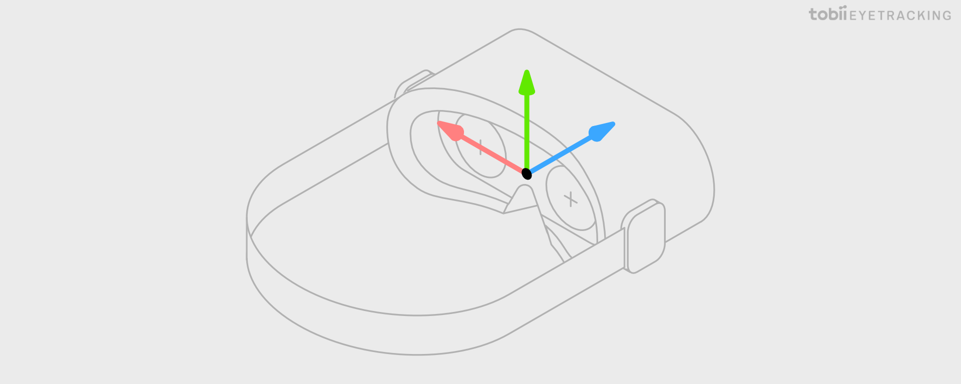
Tobii Eye Trackers natively report all data that describe 3D space coordinates in the Eye Tracking Coordinate System (ETCS). The ETCS is a cartesian, right handed system and the coordinate axes are oriented as follows: looking from a wearer’s point of view, the x-axis points horizontally towards the left side, the y-axis points vertically upwards, and the z-axis points (forward) away from the headset, perpendicular to the lenses of the headset.
The origin of the ETCS depends on the headset integration but normally it is configured to be the same point as the Head Anchor as depicted in the image below.
The unit used for all relative positions and distances is millimeter. All directions are given as unit vectors.
If you are using one of Tobii’s high level SDKs, like the Tobii XR SDK for Unity, they will internally convert from ETCS to the coordinate system used by the engine.
XR Tracking Spaces
Listed here is a brief description of the most common spaces used in a 3D graphics application. They are listed in the order a standard graphics pipeline will transform the vertices of the virtual objects to render them on a screen.
Object Space
Object Space is also commonly referred to as Local Space or Model Space.
All virtual objects are normally created in a space where the object is described as points related to an origin inside the object defined as (0, 0, 0). To be able to render the object in the virtual world, it is assigned a model matrix that describes how to transform the object to World Space.
Transforming eye tracking data to Object Space can be useful to simplify some math operations, but the more common approach is to transform the object into View Space instead.
World Space
A space where you position, rotate and scale all your virtual objects to create a 3D world. The unit is arbitrary but, especially in XR, often chosen to emulate meters to make it easier to correctly scale objects. The origin is also arbitrary but often (0, 0, 0) is chosen to represent the floor position of the desired starting point of the user.
Most simulation code operate on World Space coordinates of objects, so transforming eye tracking data to World Space is especially useful for interaction use cases. Another good use case is 3D heat maps.
Fusing Eye Tracking and Head Pose
Transforming eye tracking data to World Space requires fusion with a Head Pose. In contrast to Head Pose, which is predicted to Display Time to combat motion sickness, eye tracking data is not predicted and will be a few milliseconds old when read by the application due to system latency. When choosing what Head Pose to use for transforming eye tracking data to World Space you have two choices:
-
Use a historical Head Pose value that corresponds to the time eye tracking data was captured, see example. This will give the most accurate eye tracking data in World Space available in this frame which is suitable for recording and analysis, but if you use it to visualize a gaze ray or a gaze point, it may be perceived to lag behind due to the missing prediction that is normally applied to Head Pose.
-
Use the latest Head Pose that is predicted to Display Time, see example. This will reduce the perceived lag of visualized gaze, but at the cost of introducing temporal fusion errors. One example of how this error can manifest itself is when maintaining gaze on a stationary object in World Space while turning the head quickly. When the head turns right, the eye has to turn left to compensate. Since head is predicted and eye is not, the fused signal will point slightly to the right of the focused object.
When fusing historical Head Pose with eye tracking data, the gaze visualization remains steady when the user moves their head left and right while looking at the green stimuli point.
When fusing predicted Head Pose with eye tracking data, during a head movement the gaze visualization is initially driven by the predicted head pose to a predicted location. This makes the gaze visualization appear to catch up slightly after the head movement. This effect is most apparent when a vestibulo-ocular reflex head movement occurs (VOR), as shown in the second half of the video above.
View Space and Camera Space
View Space is also known as Head Space.
View Space represents the view of the world from the perspective of the user’s eyes. The origin of this space is the Center Eye and is used for the camera position and rotation. View Space is also the Object Space of the camera and as with normal objects in Object Space, there is a transform to World Space.
Camera Space share origin with View Space, but the coordinate axes orientation may be different. Unity, as an example, uses a left-handed coordinate system for World Space and View Space, but a right-handed, OpenGL compatible, coordinate system for Camera Space. The View Transform assigned to the camera will normally take care of this coordinate system transformation.
For stereo rendering you position one camera left and one camera right of the Center Eye. When referring to the left and right View Space in stereo rendering you can also call them Eye Space.
Transforming eye tracking data to View Space does not require any fusion with the Head Pose and is therefore the best tracking space to use for recording eye tracking data. View Space is also ideal for social use cases where you want the eyes of the user’s avatar to be looking in the same direction as the user since the Object Space of the avatar’s head has the same rotation in relation to World Space as View Space.
Clip Space
Clip Space is achieved by applying the perspective projection on Camera Space coordinates, but not the perspective divide. Clip Space is mainly used and outputted by vertex shaders to enable the GPU to cull and clip vertices outside the View Frustum.
Normalized Device Space
After applying the perspective divide on Clip Space you get normalized device coordinates (NDC). These usually range from -1 to +1 on the X and Y axes. The Z axis is handled differently between graphics APIs, both in terms of direction and whether it is normalized 0 to 1 or -1 to +1.
Screen Space
Screen Space is also known as Window Space.
Screen Space represents a 2D buffer that contains the pixels that are going to be rendered to the screen. The coordinates are either normalized 0 to 1 or in pixels. Most commonly the bottom left or top left is used as the origin.
The rasterizer will use the Viewport Transform to map NDC to Screen Space and send it as input to the fragment shader. The fragment shader output will then be used to fill the Screen Space buffer. When using single instance rendering, you actually have one double wide 2D buffer that contains both left and right Screen Spaces. This means your fragment shader will need to offset coordinates for the right Screen Space.
Most XR headsets have one Screen Space per eye, but a very wide field of view headset may want to use more than one Screen Space per eye, or more than one Viewport per Screen Space.
Transforming eye tracking data to this space is mainly useful for foveated rendering, but can also be useful if you want to know what pixel on the screen the user is looking at.